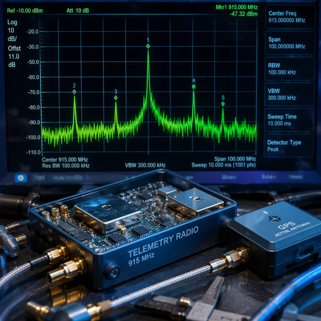
Conceptual UAV communication system with telemetry radio, antenna and ground station visualization Concept illustration
Capabilities / Communications

Communication Systems

The signal layer: radio control, telemetry data, video transmission and GNSS positioning — every link that connects the aircraft to the operator and the mission.

RoleCommand & Data Links
Frequencies433 MHz / 868/915 MHz / 2.4 GHz / 5.8 GHz
LinksRC / Telemetry / Video / GNSS
Key MetricLink Budget (dB)
Overview

Every command, every data packet, every video frame travels over RF.

A UAV's communication architecture is a stack of independent but coexisting radio links. The RC control uplink carries pilot commands with millisecond latency demands. The telemetry downlink streams aircraft state, system health and mission data to the ground station. The video feed transmits the pilot's or payload's visual perspective. And the GNSS receiver listens passively for positioning signals from orbit. Each link operates at a different frequency, power level and data rate. The system must be designed so these links do not interfere with each other — and so every link maintains its required range and reliability margin for the full mission profile.

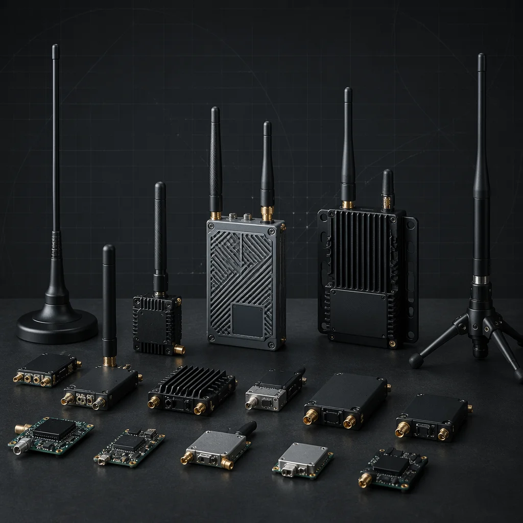
UAV telemetry radio module, antenna array, and ground station receiver on RF-transparent bench Concept illustration
Communication Layers

Four independent links, one coherent RF architecture.

Each communication layer has its own frequency band, protocol, data rate and reliability requirement. The architecture must coordinate them without mutual interference.

RC Control Link

Pilot-to-aircraft command

The most safety-critical RF path. The RC link carries stick positions, switch states and flight mode commands from the pilot's transmitter to the aircraft receiver. Modern protocols — ExpressLRS (ELRS), TBS Crossfire, FrSky ACCESS, Ghost — use spread-spectrum modulation (LoRa, FHSS) for range and interference resistance. ELRS at 2.4 GHz with 100 mW delivers 30-plus km range with 500 Hz update rate and telemetry return on a single link. Redundancy strategies include dual-frequency receivers (2.4 GHz + 868/915 MHz) and diversity antennas for spatial separation. The RC receiver is typically the only communication device that can trigger failsafe behavior — it must be configured to command a pre-defined autonomous action (RTH, loiter, land) on signal loss, not simply hold last position.

  • ELRS 2.4G
  • Crossfire 868/915M
  • Dual-band RX
  • Failsafe config
  • 500 Hz update
Telemetry Data Link

Aircraft-to-ground monitoring

Telemetry carries flight data (attitude, altitude, speed, battery, GPS), system status and mission commands between the aircraft and the ground control station. The standard protocol is MAVLink v2, a lightweight binary serialization designed for resource-constrained links. SiK radios at 433 MHz or 868/915 MHz provide transparent serial bridging at 1–5 km with dipole antennas at 100 mW. ELRS integrates MAVLink telemetry into the RC link — lower bandwidth (100–200 bytes/s) but eliminates a separate radio and antenna. For beyond-line-of-sight (BLOS) operations, 4G/LTE cellular modems tunnel MAVLink over UDP to a cloud-based ground station, and Iridium SBD provides global low-bandwidth telemetry for truly remote missions where no terrestrial infrastructure exists.

  • MAVLink v2
  • SiK radios
  • ELRS telemetry
  • 4G/LTE BLOS
  • Iridium SBD
Video Transmission

Analog and digital HD downlinks

The video link serves different priorities by application. Analog 5.8 GHz: lowest latency (sub-20 ms glass-to-glass), graceful degradation with snow rather than freeze-frame, and unlimited receivers on one transmission — the standard for FPV racing and freestyle. Digital HD (DJI O4, Walksnail Avatar, HDZero): 720p–1080p with 25–40 ms latency for compressed systems and sub-15 ms for HDZero's uncompressed approach. Digital provides dramatically better image quality for inspection and cinematography but is proprietary and typically limited to a single receiver. A separate payload camera downlink (higher bandwidth, 4G-bonded encoder) is often added for inspection applications where the pilot's FPV feed and the payload camera serve different operators with different image quality requirements.

  • Analog 5.8G
  • DJI / Walksnail
  • HDZero low-latency
  • 1080p HD
  • Payload downlink
GNSS & RTK Positioning

Passive reception, active correction

The GNSS receiver is a passive listener — it does not transmit and therefore does not contribute to RF interference, but it is sensitive to noise from other transmitters on the aircraft. Multi-constellation modules (u-blox M10, F9) tracking GPS, GLONASS, Galileo and BeiDou simultaneously provide 1.5–2.5 m horizontal accuracy. RTK (Real-Time Kinematic) with the u-blox F9P achieves 1–3 cm accuracy using correction data from a fixed base station over a telemetry radio link. Dual GNSS heading uses two receivers at a known separation to derive true heading from carrier-phase differential — immune to the magnetic interference that plagues magnetometers on large electric aircraft. Module placement is critical: mount on a mast above all conductive surfaces with an unobstructed upper hemisphere for reliable satellite tracking.

  • u-blox M10/F9
  • Multi-constellation
  • RTK 1–3 cm
  • Dual GNSS heading
  • Correction data link
Frequency Bands

Four bands, each with distinct propagation, bandwidth and regulation characteristics.

Frequency choice is the first RF architecture decision. Lower frequencies penetrate obstacles better but require larger antennas; higher frequencies support more bandwidth but are more line-of-sight dependent.

433 MHz

Maximum penetration, lowest data rate

The lowest commonly used UAV frequency. Excellent obstacle penetration — can maintain link through foliage, light structures and terrain features that block higher frequencies. Long wavelength requires larger antennas (quarter-wave = 17 cm) which can be challenging to mount on smaller airframes. Used primarily for long-range telemetry (SiK radios) where data rate is low (a few kB/s) and link reliability through obstructed paths is more important than throughput. Regulatory constraints vary significantly by region — 433 MHz is an ISM band in ITU Region 1 (Europe, Africa, Middle East) but heavily restricted in Region 2 (Americas) and Region 3 (Asia-Pacific). Always verify local regulations before specifying 433 MHz hardware.

  • Best penetration
  • Large antennas
  • Low data rate
  • SiK telemetry
  • Region-dependent
868 / 915 MHz

Range and penetration balance

The sweet spot for long-range RC control and telemetry. 868 MHz (Europe, SRD band) and 915 MHz (Americas, ISM band) offer a practical compromise: good obstacle penetration, manageable antenna size (quarter-wave = 8 cm), and moderate data rates. TBS Crossfire operates here for its 40-plus km capable RC link. LoRa modulation at these frequencies achieves extraordinary link budgets — receiver sensitivity down to -148 dBm at the lowest data rates, enabling links well beyond visual line of sight under favorable conditions. The band is shared with LoRaWAN IoT devices, smart meters and some industrial telemetry — the urban RF noise floor in this band can be higher than expected and should be surveyed for critical deployments.

  • Good penetration
  • 8 cm antenna
  • Crossfire band
  • LoRa capable
  • Shared spectrum
2.4 GHz

Global ISM band, high bandwidth

The most crowded but most capable UAV frequency. Available worldwide as an ISM band with harmonized power limits (typically 100 mW EIRP for spread-spectrum, up to 1 W for point-to-point with directional antennas). Used by ELRS, FrSky ACCESS, Spektrum DSMX and most consumer RC systems. WiFi and Bluetooth coexist here — the band is electromagnetically noisy in urban and residential areas, but modern spread-spectrum protocols handle this well through frequency hopping and error correction. Quarter-wave antenna is just 3 cm — compact enough for any airframe. The combination of global availability, compact antennas, mature chipset ecosystem and adequate bandwidth makes 2.4 GHz the default starting point for most UAV control links.

  • Global ISM
  • 100 mW typical
  • 3 cm antenna
  • ELRS / ACCESS
  • Crowded band
5.8 GHz

Maximum bandwidth, strict line-of-sight

The standard frequency for analog and digital FPV video transmission. Wide channels (20–40 MHz) support high-bandwidth video at the cost of poor obstacle penetration — even light foliage can attenuate the signal significantly. Quarter-wave antenna is only 1.3 cm, enabling compact circular-polarized antennas ideal for FPV. Power limits vary: 25 mW (CE, Europe), up to 1 W (FCC, US), with higher powers requiring a ham radio license in some jurisdictions. Circular polarization (RHCP or LHCP) is standard for 5.8 GHz FPV because it rejects multipath reflections — a critical advantage at a frequency where signals bounce readily off buildings, vehicles and terrain features. Both ends of the link must use the same polarization sense.

  • FPV standard
  • 1.3 cm antenna
  • Circular polarized
  • 25 mW–1 W
  • Line-of-sight
Range & Performance

Range is not a single number — it is link budget, data rate and environment.

These parameters define the real-world performance envelope of each communication link in the UAV stack.

Link budget (dB)The fundamental metric: Tx power (dBm) + Tx antenna gain (dBi) - free space path loss (dB) + Rx antenna gain (dBi) - cable losses (dB). Free space path loss at 2.4 GHz over 10 km is approximately 120 dB. A 100 mW (20 dBm) transmitter with 2 dBi antennas at each end yields a received signal of approximately -96 dBm — 16 dB above the ELRS -112 dBm sensitivity floor at 500 Hz, leaving margin for antenna misalignment, weather and interference. The link budget must be calculated per-link, not assumed — each frequency, data rate and antenna configuration produces a different budget.
Data rate vs. range trade-offThese trade against each other. LoRa-based systems (ELRS, Crossfire) offer multiple rate modes: 500 Hz at shorter range with lower sensitivity, stepping down to 50 Hz or 25 Hz for maximum range where the lower data rate enables a lower sensitivity floor. A SiK radio at 433 MHz may deliver 64 kbps at 1 km but only 2 kbps at 10 km. Video links are bandwidth-hungry but latency-sensitive — the acceptable range is where the video bitrate floor (typically 5–10 Mbps for HD) can be maintained, not where the bare carrier is still detectable above noise.
Interference & RF noise floorThe theoretical free-space range is almost never achieved in practice because the RF noise floor is not the thermal noise floor. Urban 2.4 GHz noise floors are 10–20 dB above thermal due to WiFi, Bluetooth, microwave ovens and IoT devices. Industrial sites add noise from VFDs (variable frequency drives), switching power supplies and arc welding equipment. A site survey with a spectrum analyzer — even a low-cost USB SDR dongle — before finalizing the frequency plan is good practice for critical deployments where link reliability directly affects safety or data quality.
Antenna gain and directivityHigher gain means more range — but only in the direction the antenna is pointed. An 8 dBi patch antenna on the ground station provides 6 dB more gain than a 2 dBi dipole, quadrupling effective range in free space. But the beam is narrow (typically 60–70 degrees) — the antenna must be pointed at the aircraft. Omnidirectional antennas avoid pointing requirements but sacrifice gain. The optimal ground station setup is often a diversity receiver with one directional (patch/helical) and one omnidirectional antenna, automatically selecting the stronger signal path.
Regulatory compliance by regionFrequency, power and modulation constraints vary by jurisdiction. 2.4 GHz at 100 mW EIRP is harmonized globally. 868 MHz SRD is limited to 25 mW (500 mW with duty cycle restrictions) in Europe. 915 MHz ISM allows up to 1 W with spread spectrum in the US. 5.8 GHz FPV is 25 mW CE versus up to 1 W FCC. Operating outside licensed parameters can result in enforcement action — particularly in aviation bands or near sensitive receivers (radio astronomy, air traffic control radar). Know the local regulations before specifying RF hardware; compliance is a design input, not an afterthought.
Antenna Selection

Antennas are not accessories — they define the RF path.

Antenna type, gain, polarization, placement and cabling determine how much of the transmitter power actually reaches the receiver. The best radio with a poorly chosen or placed antenna performs worse than a modest radio with an optimized antenna system.

Omnidirectional (Aircraft Side)

Linear dipole, whip, sleeve

Radiation pattern is roughly a doughnut — strong in all horizontal directions, nulls at the tips. The standard antenna for RC receivers because the aircraft orientation relative to the ground station is constantly changing. Quarter-wave (30 mm at 2.4 GHz, 82 mm at 868 MHz) is the most compact; half-wave dipoles offer 2.15 dBi gain at twice the length. Sleeve dipoles and inverted-F antennas provide a ground-plane-independent option for mounting on non-conductive airframes or away from carbon fiber surfaces. Placement priority: as far from conductive structure as practical, with the antenna axis vertical when the aircraft is in level flight to match the typical ground station antenna polarization. Two receiver antennas should be mounted at 90 degrees to each other for polarization diversity.

Directional (Ground Side)

Patch, helical, Yagi

Concentrate receiver sensitivity or transmitter power in a narrow beam toward the aircraft. Patch antennas: flat, compact, 8–14 dBi gain, 60–70 degree beamwidth — the workhorse of ground station receive antennas for medium-range operations. Helical: circular-polarized, 9–14 dBi gain, excellent axial ratio for CP video reception, narrower beamwidth than patch — preferred for long-range FPV video where multipath rejection matters. Yagi: highest gain (12–18 dBi) with very narrow beamwidth (30–40 degrees), used for extreme-range telemetry and RC links where the aircraft flies a predictable path. All directional antennas require pointing — either manually with a tripod, or automatically via an antenna tracker that follows the aircraft's GPS position telemetered to the ground.

Circular Polarized

Cloverleaf, pagoda, helical

Circular polarization (CP) rotates the electric field as the wave propagates, making it resistant to multipath interference — reflected signals reverse their polarization sense and are rejected by the receiving antenna. This is critical for FPV video at 5.8 GHz where signals bounce off buildings and terrain. CP antennas have approximately 3 dB loss compared to linear (half the power is in the orthogonal polarization) but the multipath rejection typically provides a net improvement in video link quality. RHCP and LHCP are not interchangeable — both ends of the link must use the same sense. Cloverleaf and pagoda designs are the standard aircraft-side CP antennas; helical antennas provide high-gain CP reception on the ground side for long-range video.

Placement & Coaxial Cabling

Location, orientation, and cable loss

Antenna placement on the aircraft directly affects link quality and must be treated as an engineering decision, not an afterthought. Separation between antennas (RC, telemetry, video, GPS) should be maximized to reduce near-field coupling and receiver desensitization. Keep antennas away from carbon fiber plates, batteries and metal payloads that shadow or reflect RF. GPS antennas need an unobstructed upper hemisphere — mounting under a carbon fiber plate or next to a GoPro guarantees poor satellite reception. Coaxial cable loss increases with frequency and cable length: RG316 loses approximately 1.5 dB/m at 2.4 GHz and 2.5 dB/m at 5.8 GHz. Cable runs should be as short as possible; for longer runs, use lower-loss cable (RG402 semi-rigid, LMR-195) and accept the weight penalty. Every 3 dB of cable loss halves the effective transmitter power or receiver sensitivity at that antenna port.

Related Capabilities

Communications connect to flight control and payload.

Every radio link terminates at the flight controller. The comms architecture is defined by the FC's serial port count, protocol support and failsafe behavior.

Flight Control

UART allocation and protocol mapping

Every radio link — RC receiver, telemetry radio, GPS module — occupies a UART on the FC. The FC pinout and UART count constrain how many and which types of communication devices can be connected simultaneously. Protocol selection at the FC level (SBus, CRSF, MAVLink) must match the receiver and telemetry radio output.

Flight Control
Payload & Kits

Payload video and data paths

Payload cameras, sensors and gimbals often require their own video downlink or data telemetry path. The frequency plan, antenna placement and bandwidth allocation must accommodate the payload's communication needs alongside the aircraft's control and telemetry links.

Payload & Kits
Start With the Signal Architecture

Bring the operational range and link requirements.

Tell us the maximum operational range, video needs, telemetry requirements and any BLOS or redundancy goals. We will map the frequency plan, link budget and antenna architecture for your build.