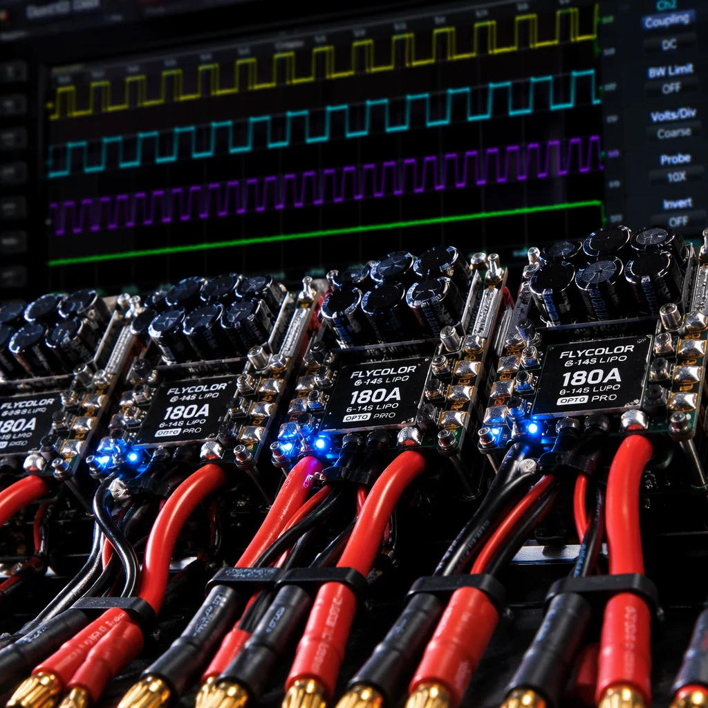
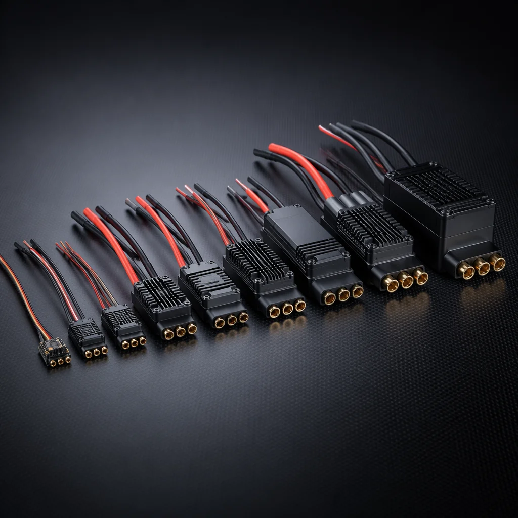
Conceptual UAV ESC board and power distribution system visualization Concept illustration
Capabilities / ESC & Power

ESC & Power Systems

The energy path from battery terminal to motor winding: speed controllers, power distribution, battery architecture and wiring — selected as one coordinated power system.

RoleEnergy Conversion
ProtocolsDShot / PWM / CAN
Voltage Range4S–12S (14.8–50.4 V)
Key InterfacesFC, Motor, Battery
Overview

Every watt matters between battery and propeller.

The power path — battery to PDB to ESC to motor — is a chain of decisions that affects flight time, thrust response, electrical noise and thermal behavior. Selecting an ESC is not a standalone choice. It is the midpoint of a power architecture that must be consistent from cell chemistry to motor winding.

Electronic speed controller with MOSFET array, capacitor bank, and signal input pads on engineering bench Concept illustration
ESC Types & Protocols

The communication layer between FC and motor.

ESC protocol determines throttle resolution, update rate, telemetry availability and noise immunity — each with different trade-offs for different aircraft categories.

BLHeli_32 / AM32

DShot digital protocol

Digital ESC protocol operating at DShot300–DShot1200 with 10.7–42.6 kbps data rates. Eliminates throttle calibration, provides CRC error checking and supports bidirectional DShot for RPM telemetry. BLHeli_32 and its open-source successor AM32 cover the majority of multi-rotor ESCs from 20 A to 80 A per channel. RPM filtering in Betaflight and INAV uses this telemetry stream to suppress motor-noise bands in the gyro data — a significant improvement in flight smoothness on smaller airframes.

  • DShot300–1200
  • RPM telemetry
  • CRC protected
  • 20–80 A
CAN ESC

Distributed power architecture

CAN bus ESCs replace individual PWM/DShot signal wires with a two-wire differential bus. Each ESC reports current, voltage, temperature, RPM and error status back to the flight controller over the same bus. This architecture reduces wiring complexity on larger aircraft (8+ motors), enables individual motor health monitoring and supports firmware updates over CAN. Common in ArduPilot and PX4 builds above 25 kg all-up weight where per-motor diagnostics matter.

  • CAN bus
  • Per-motor telemetry
  • Reduced wiring
  • OTA firmware
PWM ESC

Universal analog fallback

Standard 50–400 Hz PWM input — the most widely compatible ESC interface. Used on fixed-wing motor ESCs, large multi-rotor ESCs (80 A+) and any application where protocol compatibility across mixed hardware matters more than update rate. Requires throttle calibration per ESC. Typically combined with a separate BEC for flight controller and servo power. Still the default for industrial fixed-wing builds where the autopilot outputs standard PWM to both motor and servo channels.

  • 50–400 Hz
  • Universal
  • Fixed-wing
  • 80 A+ capable
4-in-1 / AIO

Integrated ESC boards

Four ESCs on a single PCB sharing power input and signal routing. Common in 3–7 inch multi-rotors below 2 kg. Reduces wiring, saves weight and simplifies the build — but concentrates thermal load and creates a single point of failure for all four motors. Stack-mounted with the flight controller for a compact electronics package. Available in 20×20 mm and 30.5×30.5 mm mounting patterns with current ratings from 15 A to 65 A per channel.

  • 4-in-1
  • 20×20 / 30.5×30.5
  • 15–65 A/ch
  • Compact
Current & Voltage Architecture

Size the power path for the load — with headroom.

Current rating and voltage selection are driven by motor draw, not battery label. Underspecifying either leads to thermal shutdown, voltage sag or failure.

Voltage (cell count)4S (14.8 V) for sub-250 g and 3-inch builds. 6S (22.2 V) standard for 5–7 inch multi-rotors. 8S (29.6 V) for 7–10 inch and heavy-lift. 12S (44.4–50.4 V) for industrial platforms above 15 kg. Higher voltage reduces current for the same power — less I²R loss, cooler wiring, more efficient.
Current ratingESC current rating should exceed motor max continuous draw by 20–30%. A motor pulling 35 A at full throttle on 6S needs a 45–50 A ESC. Peak (burst) ratings are for seconds only — sustained hovering and climb profiles must stay within the continuous rating.
Thermal managementESC temperature rise depends on current, airflow and ambient temperature. Enclosed airframes and high-altitude operation (thinner air, less convective cooling) both demand more conservative current derating. Heatsink and active cooling become necessary above 80 A continuous per channel.
Power Distribution

Get power from the battery to every consumer.

Power distribution is not just a PCB or wiring harness — it is the electrical architecture that feeds ESCs, flight controller, servos, payload and accessories at their required voltages.

PDB and wiring harness

A power distribution board (PDB) takes battery voltage and routes it to each ESC pad with appropriate copper weight (2–4 oz) for the total system current. On smaller builds an AIO FC+ESC stack eliminates the separate PDB. On larger aircraft a centralized PDB or a distributed wiring harness with XT60/XT90/AS150 connectors feeds each ESC individually. Wire gauge follows the current path: 12–14 AWG for battery leads, 16–18 AWG for individual ESC power feeds on sub-10 kg platforms.

BEC and voltage regulation

A battery eliminator circuit (BEC) steps battery voltage down to 5 V, 9 V or 12 V for the flight controller, receiver, servos and accessories. Standalone BECs (switching, 3–10 A) provide cleaner power than integrated ESC BECs and isolate the FC supply from motor-noise spikes. Servo-heavy fixed-wing builds need separate BECs rated for peak servo stall current. Redundant BEC configurations add a second regulated supply with diode-OR for power-path failover on critical platforms.

Battery Selection

Chemistry, capacity and C-rating define the energy budget.

The battery determines flight endurance, peak power availability and physical weight — the single heaviest component on most electric UAVs.

LiPo (lithium polymer)High discharge rates (30 C–120 C continuous) at the cost of lower energy density. The standard for multi-rotors where burst power matters. 6S 22.2 V packs from 1000 mAh (sub-250 g) to 22,000 mAh (heavy-lift) cover most builds. Requires careful storage voltage management and physical protection from puncture.
Li-Ion (lithium-ion)Higher energy density (200–260 Wh/kg vs 140–180 Wh/kg for LiPo) but lower discharge rates (5 C–15 C continuous). Preferred for long-endurance fixed-wing mapping platforms where constant cruise current is low. 6S Li-Ion packs built from 18650 or 21700 cells can deliver 60–90 minute flight times on efficient airframes.
Capacity vs. weightBattery mass scales roughly linearly with capacity at a given cell count. A 6S 5000 mAh LiPo weighs approximately 700–800 g. Doubling capacity approximately doubles weight — but does not double flight time because the aircraft must lift the added mass. The endurance optimum is found at the point where marginal energy gain is offset by the power required to lift it.
C-rating and real drawC-rating times capacity gives the theoretical max current. In practice, sustained draw should stay well below the continuous C-rating to limit voltage sag and heating. A 5000 mAh pack rated 50 C claims 250 A — but sustained draw above 100 A (20 C) will cause significant sag. Temperature rise above 60 C degrades pack life rapidly.
Selection Guidance

Power architecture by aircraft type.

Common power-system starting points for different UAV categories.

Sub-250 g microAIO FC+ESC board, 3S–4S 450–850 mAh LiPo, integrated BEC. Weight is the overriding constraint — every gram saved on power components extends flight time.
5-inch freestyle / cine4-in-1 BLHeli_32/AM32 ESC 45–55 A, 6S 1300–1800 mAh LiPo, stack-mounted with FC. DShot600 with bidirectional RPM filtering for smooth flight video.
7–10 inch heavy-liftIndividual ESCs 50–80 A or 4-in-1 65 A board, 6S–8S 5000–10000 mAh LiPo, separate switching BEC. Focus on thermal headroom and low-ESR capacitor banks at the PDB.
Industrial multi-rotor (15+ kg)CAN bus ESCs 80–120 A per channel, 12S 16000–22000 mAh LiPo or Li-Ion pack, distributed wiring harness with AS150 connectors. Redundant BEC, per-motor current monitoring, active cooling.
Fixed-wing enduranceSingle PWM ESC 40–60 A, 6S Li-Ion 10000–21000 mAh pack, separate BEC for servo rail. Cruise current is the design point — the ESC must be efficient at 30–50% throttle, not just peak.
Related Capabilities

Power connects to control and motion.

The power architecture is the bridge between the flight controller's commands and the propulsion system's response.

Flight Control

Protocol and voltage handoff

ESC protocol selection (DShot, PWM, CAN) is defined by FC output capability. BEC voltage must match FC input spec. Current sensor calibration ties the power path into the flight controller's battery monitoring.

Flight Control
Propulsion

Motor current defines ESC sizing

ESC current rating is sized to motor max draw with headroom. Motor-ESC-prop matching is a single optimization problem — change one and the other two shift.

Propulsion
Start With the Power Path

Bring the aircraft size and performance targets.

Tell us the all-up weight, motor count, desired flight time and payload power requirements. We will map the voltage architecture, ESC selection and distribution design.