 Concept illustration
Design Guides
Component selection frameworks, system architecture patterns, and integration best practices for UAV engineering teams building mission-critical aircraft.
Why Design Guides
Making Informed Component Decisions
Selecting the right components for a UAV system is a multi-dimensional engineering challenge. Every decision — from the flight controller microcontroller to the gauge of power distribution wiring — cascades through weight, endurance, reliability, and total system cost. These guides distill our engineering team's experience across hundreds of aircraft configurations into actionable decision frameworks.
Whether you are designing an agricultural spraying multi-rotor, a long-endurance fixed-wing survey platform, or a research aircraft with custom sensor payloads, these guides provide the technical depth needed to evaluate tradeoffs and converge on a well-matched component set.
Guide Library
Six Core Engineering Domains
Each guide addresses a critical subsystem. Read them in sequence for a full-system perspective, or jump directly to the domain most relevant to your current design phase.
1. Flight Controller Selection
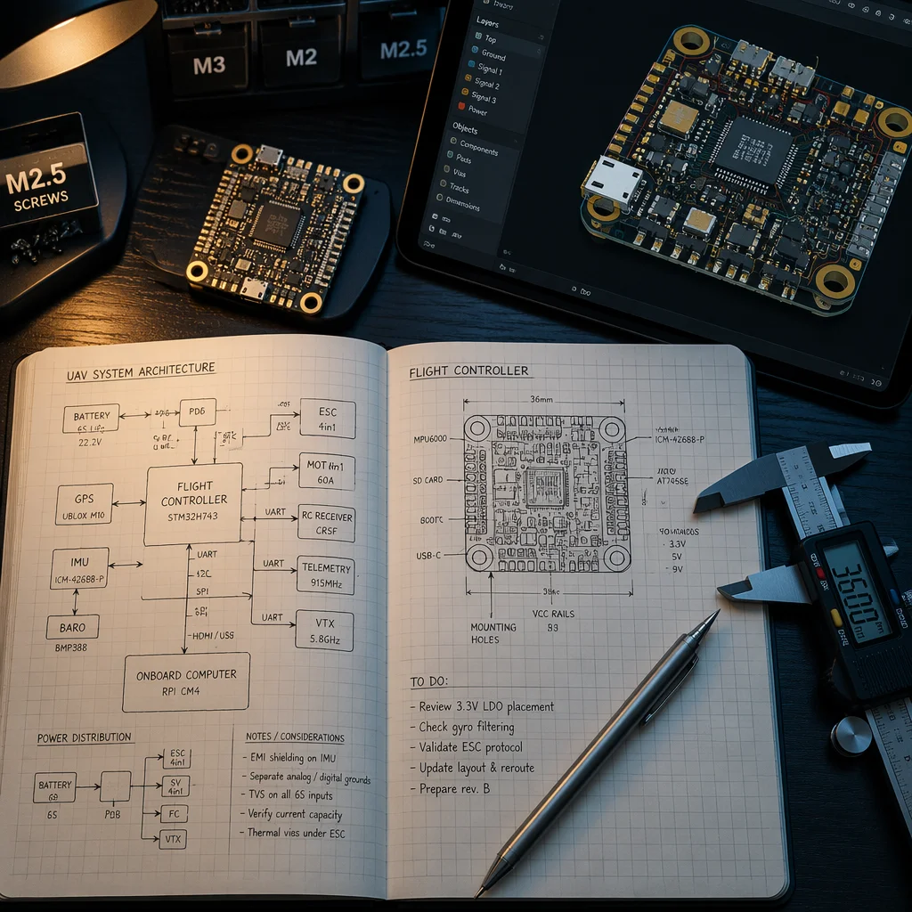
Processor architecture, sensor fusion, firmware ecosystem compatibility, and redundancy topologies. Covers MCU performance tiers, IMU selection criteria (vibration rejection, update rate, redundancy), barometer and GNSS integration, and the tradeoffs between open-source (ArduPilot, PX4) and proprietary flight stacks for different mission profiles.
Key considerations: loop rate vs. computational load, triple-redundant IMU architectures, RTK GNSS precision tiers, and hardware-in-the-loop testing compatibility.
2. ESC & Motor Matching
Voltage, current, and protocol alignment across the propulsion chain. Covers ESC firmware options (BLHeli_32, AM32, proprietary FOC), communication protocols (DShot, CAN, PWM), and motor sizing methodology — KV selection, stator dimensions, and thermal derating under sustained load.
Key considerations: thermal headroom at max continuous current, active freewheeling efficiency gains, CAN vs. DShot for large aircraft, and motor-ESC connector standardization.
3. Power System Architecture
Battery chemistry selection, power distribution bus design, BMS integration, and wiring gauge calculations. Covers LiPo vs. Li-Ion vs. semi-solid-state tradeoffs for different endurance and discharge-rate requirements, PDB architecture (centralized vs. distributed), and voltage sag compensation strategies.
Key considerations: cell internal resistance at target current draw, connector current ratings with safety margin, parallel battery configurations, and BMS communication bus selection.
4. Communication Stack Design
Radio frequency selection, telemetry architecture, data link redundancy, and antenna placement. Covers frequency band tradeoffs (433 MHz, 868/915 MHz, 2.4 GHz) for range vs. bandwidth, dual-link redundancy patterns, and antenna diversity strategies for composite airframes.
Key considerations: link budget calculations, antenna polarization matching, RF-transparent airframe materials, and spectrum regulatory compliance by region.
5. Airframe Integration
Materials selection, component mounting geometries, vibration isolation techniques, and center-of-gravity optimization. Covers carbon fiber vs. aluminum vs. composite frame tradeoffs, vibration damping materials and mounting patterns, and CG calculation methodology for asymmetric payload configurations.
Key considerations: frame resonance frequencies vs. motor RPM bands, fastener torque specifications for carbon fiber, and modular vs. monolithic frame design for field repair.
6. Payload Interface Design
Mechanical mounting standards, electrical power and signal interfaces, and data protocol integration. Covers quick-release mechanism selection, gimbal communication protocols (PWM, SBUS, CAN, serial), and payload power budgeting within the total aircraft power envelope.
Key considerations: hot-swap payload connector specifications, data bandwidth for real-time payload telemetry, and EMI isolation between payload and aircraft electronics.
File Format Requirements
When engaging our engineering team for component selection support or custom integration work, providing design files in standardized formats accelerates the review and quotation process.
 Concept illustration
Mechanical CAD
- STEP (.stp / .step) — Preferred for 3D models; universal compatibility across CAD platforms
- DXF (.dxf) — For 2D profiles, mounting patterns, and frame plate layouts
- PDF (.pdf) — Dimensioned drawings with tolerances for quick review
Configuration & Data
- JSON (.json) — Preferred for component BOM, configuration parameters, and telemetry schema definitions
- XML (.xml) — For parameter files and flight controller configuration exports
- CSV (.csv) — Acceptable for motor thrust tables and test data
Lessons from the Field
Common Design Pitfalls
Our engineering team has seen these mistakes repeated across dozens of projects. Avoiding them early saves weeks of rework and thousands in component costs.
- Under-specifying ESC current rating. Operating at or near the rated continuous current leaves zero thermal margin. Apply at minimum a 1.3x derating factor for sustained hover and a 1.5x factor for aggressive maneuvering.
- Ignoring vibration resonance. A motor-propeller combination that excites frame resonant frequencies can saturate IMU sensors and degrade flight controller performance — even on otherwise well-designed aircraft.
- Mismatched connector standards across subsystems. Different vendors using different connectors for the same voltage rail leads to adapter proliferation, added weight, and additional failure points. Standardize connectors early in the design phase.
- Insufficient power distribution margin. Designing the PDB for nominal current draw ignores voltage sag, connector heating, and inrush current during rapid throttle changes. Size traces and connectors for peak, not average.
Engineering Support
Need Design Help?
Our applications engineering team can review your concept, recommend component pairings, and provide preliminary BOM costing — typically within 3 business days.