 Concept illustration
LiDAR survey and mapping platform
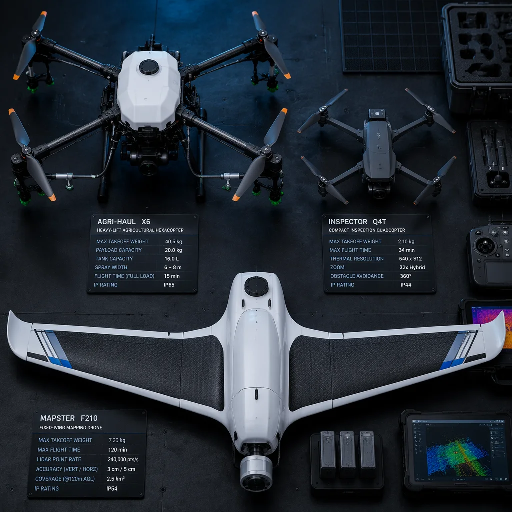
An engineering reference for a long-endurance fixed-wing VTOL platform configured for high-density LiDAR mapping and photogrammetry. This document covers the component architecture, sensor integration logic, vibration isolation strategy, and communication stack — not as a customer case study, but as a reusable engineering framework for teams building similar survey-grade UAV systems.
Project Overview
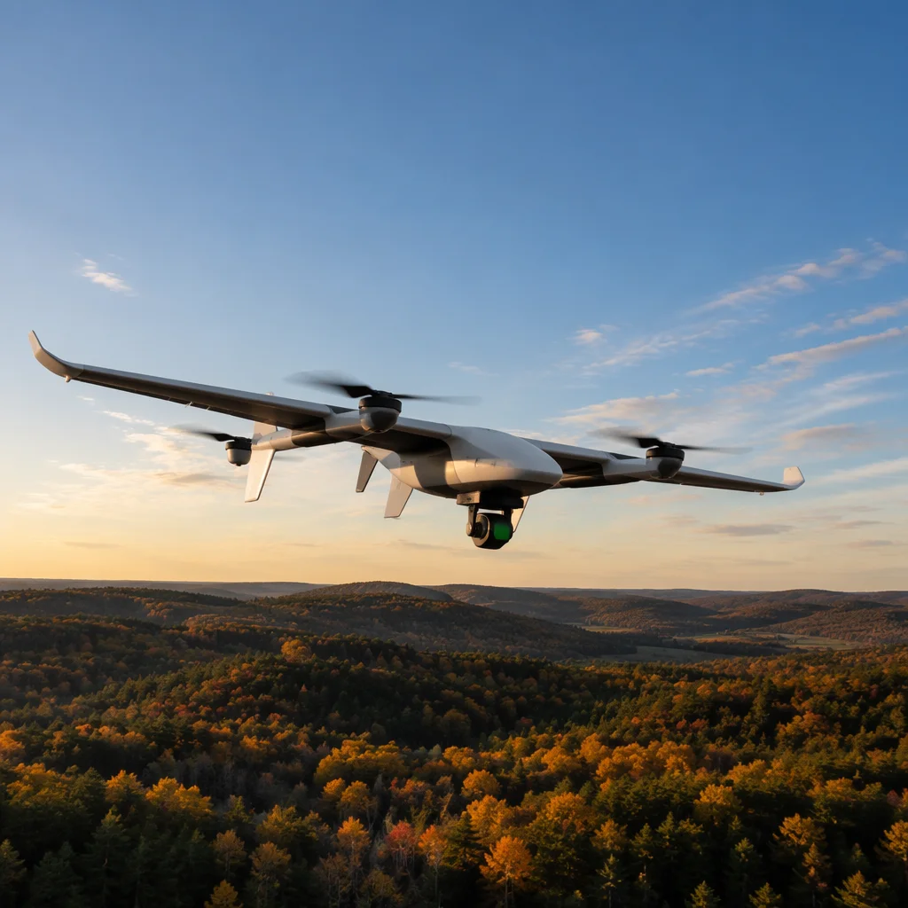
This platform is designed around a fixed-wing VTOL airframe with a target endurance of 120 minutes and a payload capacity of 5 kg. The mission profile assumes corridor mapping and area survey operations at 100–120 m AGL with a cruise speed of 16–18 m/s. The airframe transitions between vertical takeoff/landing and fixed-wing cruise via four lift motors and a dedicated pusher motor, enabling operation from unprepared sites without runway infrastructure.
 Concept illustration
The primary payload is an integrated LiDAR scanner with an RGB camera for simultaneous point cloud and orthophoto capture. Secondary payload provisions include a multispectral sensor bay with a standardised mechanical and electrical interface for mission-swappable sensor heads. The platform is intended to serve survey teams conducting topographic mapping, vegetation canopy analysis, and corridor inspection over linear infrastructure assets.
The design emphasis is on component interoperability — flight controller, RTK receiver, LiDAR IMU, and onboard computer share a common time-synchronisation bus, ensuring that every laser return is accurately geo-referenced without post-processing drift. This architecture reduces the integration burden that typically arises when mixing components from different manufacturers with incompatible timing protocols.
Component Architecture
Flight Controller & Navigation
The core is a Cube Orange+ running ArduPilot with fixed-wing VTOL firmware. Navigation relies on a Here3 RTK GNSS unit providing centimetre-level positioning via local NTRIP correction. A redundant external compass and dual barometers supply the sensor fusion needed for reliable transition between hover and forward flight modes. The flight controller outputs PWM to the lift motors and a dedicated CAN channel to the pusher ESC, allowing independent throttle curves for vertical and cruise propulsion.
Payload Integration — LiDAR + RGB
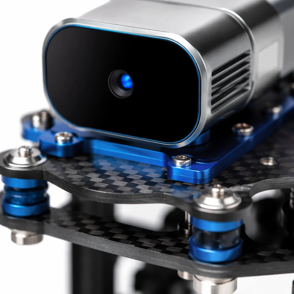
The payload bay accommodates a Hesai PandarXT mid-range LiDAR (360-degree FOV, 120 m range at 10% reflectivity) paired with a 42 MP Sony A7R IV full-frame camera. Both sensors are mounted on a shared aluminium isolation plate decoupled from the airframe via four wire-rope isolators. The LiDAR's internal IMU shares a hardware synchronisation line with the flight controller's GPS PPS output, ensuring that every laser pulse timestamp aligns with the RTK position solution. An onboard NVIDIA Jetson Orin NX handles real-time point cloud registration and stores raw data to a 2 TB NVMe SSD.
 Concept illustration
Communication Stack
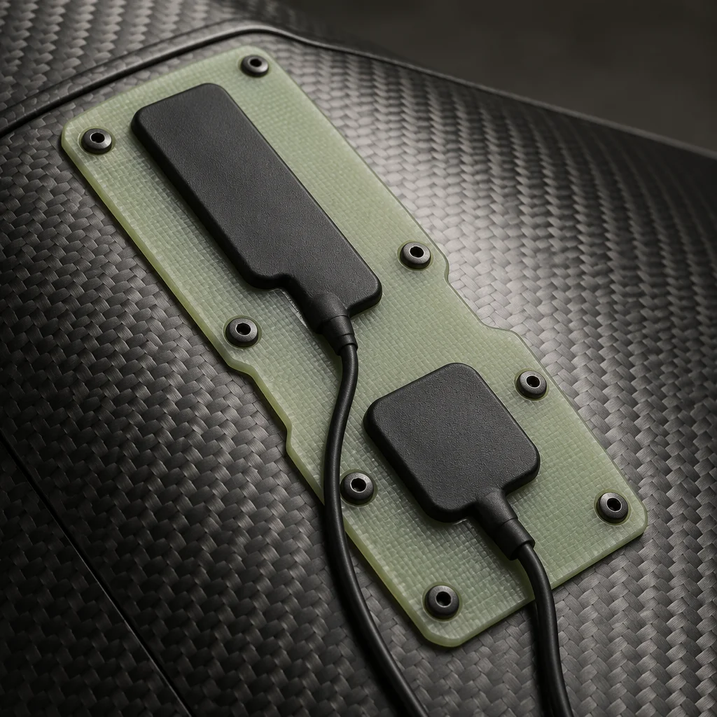
A dual-band architecture separates command-and-control from payload telemetry. The 868 MHz RFD900x link carries MAVLink telemetry and RC override at ranges up to 20 km, while a 5.8 GHz Ubiquiti Bullet AC link streams the LiDAR point cloud preview and camera video feed to the ground control station. Both antennas are embedded within the composite airframe to preserve the laminar flow over the fuselage and reduce drag. An Iridium satellite short-burst modem provides position reporting as a fail-safe for beyond-visual-line-of-sight operations.
 Concept illustration
Power System
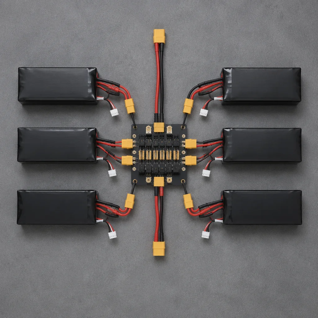
Endurance targets drive the power architecture. A 6S8P Li-Ion pack built from Samsung 50E cells delivers 40,000 mAh at a nominal 22.2 V — approximately 888 Wh of onboard energy. A central PDB with Hall-effect current sensors monitors total system draw and individual branch currents for the pusher motor, lift motors, payload, and avionics. The VTOL motors draw from the same pack through dedicated ESCs, with the flight controller managing a power budget that limits combined lift-motor duty to the transition phase only, preserving cruise energy for survey legs.
 Concept illustration
Vibration Isolation
LiDAR point cloud quality is directly degraded by high-frequency vibration from the propulsion system. We specify a two-stage isolation approach: the motor mounts use silicone grommets sized to the dominant frequency of each lift rotor (approximately 120 Hz at hover RPM), and the payload plate floats on four GG-type wire-rope isolators with a natural frequency below 15 Hz. This arrangement attenuates motor-induced vibration by approximately 30 dB at frequencies above 80 Hz, well within the noise tolerance of the LiDAR's internal IMU. The isolator mounts bolt to the airframe's main carbon fibre spar, distributing the 5 kg payload mass across the primary load path rather than cantilevering from a secondary structure.
Key Engineering Decisions
Sensor Mounting Tradeoffs
The LiDAR scanner could have been mounted in a belly pod for an unobstructed 360-degree field of view, or in a nose-cone integration for aerodynamic cleanliness. A belly pod simplifies cabling and provides the best scan geometry for corridor mapping, but adds approximately 0.8 kg of structural mass and increases parasite drag by an estimated 12%. The nose integration preserves cruise efficiency but requires a cutout in the composite shell and a custom radome that is transparent to 905 nm laser wavelength. For survey missions where endurance directly determines hectares covered per flight, the nose-integration path yields a higher area-throughput despite the manufacturing complexity.
Antenna Placement on Composite Airframe
Carbon fibre is conductive and acts as an RF shield. The fuselage uses a fibreglass-epoxy layup in the antenna bay section to create an RF-transparent window, with the 868 MHz and 5.8 GHz antennas mounted on a shared PCB carrier that maintains minimum 1/4-wavelength separation. The GPS patch antenna sits in a dedicated ground-plane cavity on the upper fuselage, isolated from the carbon fibre by a 15 mm foam standoff. This arrangement was validated with a VNA sweep across 400 MHz to 6 GHz, confirming return loss below -10 dB across all operating bands.
Power Budget Balancing
The 888 Wh battery supports approximately 85 W cruise draw (pusher motor at 55% throttle, avionics, and payload), yielding a theoretical 10.4 hours of cruise flight. In practice, the VTOL transition and a 20% reserve reduce usable endurance to 120 minutes of survey operation. The LiDAR and onboard computer consume a combined 38 W, while the flight controller, RTK receiver, and telemetry radios draw 12 W. The lift motors spike to 1,200 W combined during takeoff and transition but operate for under 90 seconds per flight. The resulting energy per mission breaks down as roughly 68% cruise propulsion, 22% payload systems, 7% avionics, and 3% transition energy. Moving to higher-energy-density cells (e.g., Samsung 50S at 21700 format) could extend endurance by 15–18% within the same pack volume.
Engineering Lessons & Education Disclaimer
Several integration challenges surfaced during the prototyping phase that are worth documenting for teams pursuing similar architectures. Time synchronisation between the LiDAR IMU and the RTK GNSS receiver required a dedicated PPS line — relying on software timestamps over MAVLink introduced 15–30 ms of jitter that produced visible striping in the point cloud. The carbon fibre spar that carries the payload isolators needed a localised reinforcement patch at the bolt locations; without it, micro-cracking appeared around the fastener holes after approximately 50 flight cycles. Battery cell balancing across the 48-cell Li-Ion pack proved sensitive to the wiring harness layout: cells at the far end of the series string drifted by up to 45 mV per cycle when the balance leads exceeded 300 mm in length.
Education disclaimer. This engineering reference is provided for educational and informational purposes. It describes a representative UAV system architecture, component selection methodology, and integration approach. It is not a certified aircraft design, build manual, or flight-ready specification. Any team reconstructing a similar platform must conduct their own structural analysis, RF compliance verification, and flight safety assessment appropriate to their operating jurisdiction and mission profile. EMS Drone assumes no liability for designs derived from this reference material.
Build a Similar Platform
Discuss your mapping UAV architecture
Share your survey requirements — area throughput, point density targets, operating altitude, and endurance goals — and our engineering team will prepare a preliminary component recommendation and integration roadmap.