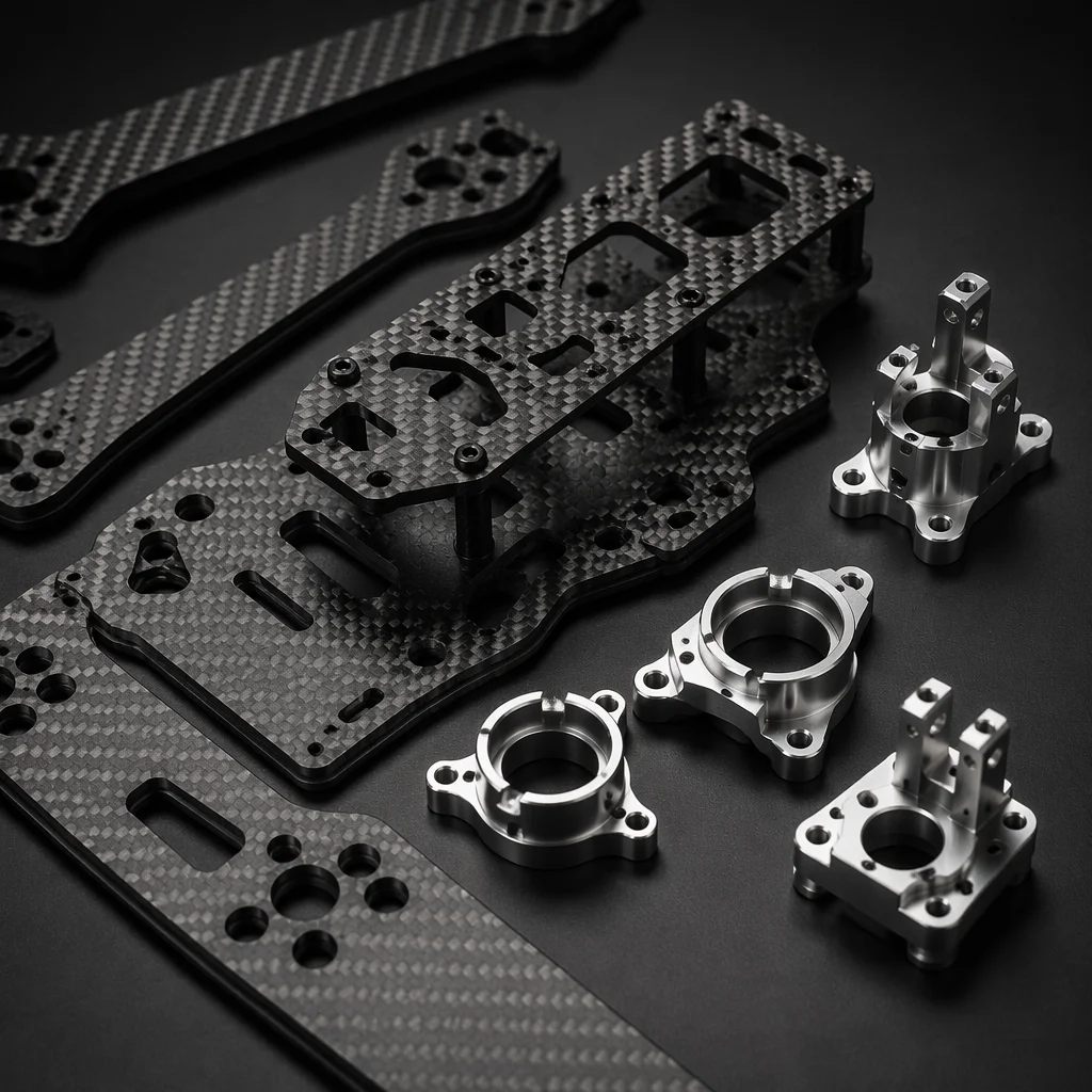
Teams building commercial UAVs spend weeks comparing flight controllers (see matching flight controllers and ESCs), ESCs and motor curves. The airframe often arrives last — chosen for price or availability rather than mission fit. That sequence has consequences. The frame touches every other subsystem: it determines where vibration energy goes, how RF signals propagate, what happens in a hard landing and how field repairs get done.
Why material choice shapes the aircraft
The airframe is not just a structural shell. It sets the weight budget available for payload and battery (see UAV powertrain matching and weight allocation). It defines vibration transmission paths from motors to IMUs and cameras. It influences EMI shielding for GPS, compass and radio antennas. It determines crash behavior — whether energy dissipates through elastic deformation or brittle fracture. And it governs repairability: can a damaged arm be swapped in the field, or does the entire frame need factory service?
Material choice should follow from mission requirements, not aesthetic preference or what is cheapest per square meter. A mapping drone that needs mechanical stability for photogrammetry has different priorities from a delivery drone that needs impact toughness for repeated landings.
Carbon fiber: king of strength-to-weight
Carbon fiber composites dominate high-performance UAV frames for a reason. Typical 3K twill-weave laminates deliver tensile strength in the 600–900 MPa range at densities around 1.5 g/cm³ — roughly five times the specific strength of 6061 aluminum. Stiffness is similarly exceptional, which directly benefits precision applications: a rigid frame keeps camera gimbal mounts and LiDAR sensors in known positions through aggressive maneuvers.
This performance comes with trade-offs. Carbon fiber is electrically conductive and can act as an unintended RF shield or reflector — a real concern for GPS patch antennas and magnetometer compasses mounted inside or near carbon plates. Its failure mode is brittle: a carbon arm that exceeds its elastic limit does not bend, it fractures. Field repair typically requires epoxy, vacuum bagging and cure time, not a hex key. Cost per frame is higher than aluminum or G10 equivalents.
Best for: professional multi-rotors, fixed-wing wings and tail booms, mapping and LiDAR platforms, any weight-critical application where payload fraction matters.
Aluminum (6061-T6 / 7075-T6): predictable and tough
Aerospace-grade aluminum brings predictability that composites sometimes lack. 6061-T6 offers tensile strength around 276 MPa at 2.7 g/cm³. 7075-T6 pushes higher — roughly 510–540 MPa — at a modest cost premium. Both are heavier than carbon for equivalent stiffness, but neither surprises you: properties are isotropic, well-documented and consistent batch to batch.
The real advantage is toughness. Aluminum yields before it breaks. A hard landing that shatters a carbon arm may leave an aluminum bracket bent but structurally intact — the frame absorbs energy through plastic deformation. Aluminum is electrically conductive, which can be managed with proper grounding rather than avoided. Tapping threads directly into aluminum is straightforward; no bonded inserts required.
Best for: motor mounts, landing gear assemblies, heavy-lift frame center plates, industrial enclosures and any joint that needs threaded fasteners in a high-vibration environment.
G10/FR4 (fiberglass epoxy): the practical middle ground
G10 and FR4 — glass-fabric-reinforced epoxy laminates — occupy a useful space between carbon and aluminum. Tensile strength runs 300–400 MPa at roughly 1.8 g/cm³, placing it closer to carbon than aluminum on specific strength. But the headline feature is RF transparency: G10 does not block or distort GPS, 2.4 GHz control or 5.8 GHz video signals the way carbon fiber can. This makes it the default choice for GPS mast plates, antenna mounting brackets and any structural member that sits directly above or below an RF element.
Cost is another factor. G10 sheet is substantially cheaper than carbon fiber plate of equivalent thickness. It machines cleanly on standard CNC routers without the abrasive tool wear that carbon fiber causes. The downsides are real: lower overall stiffness means thicker sections for the same rigidity, adding weight. Poor drilling technique or dull tooling can cause delamination at the exit side of holes. And G10 does not have the premium look that some commercial customers expect.
Best for: prototype and development frames, GPS and antenna mounting plates, electrical isolation boards between conductive assemblies, cost-sensitive production volumes.
 Concept illustration
Decision framework: which material fits your mission
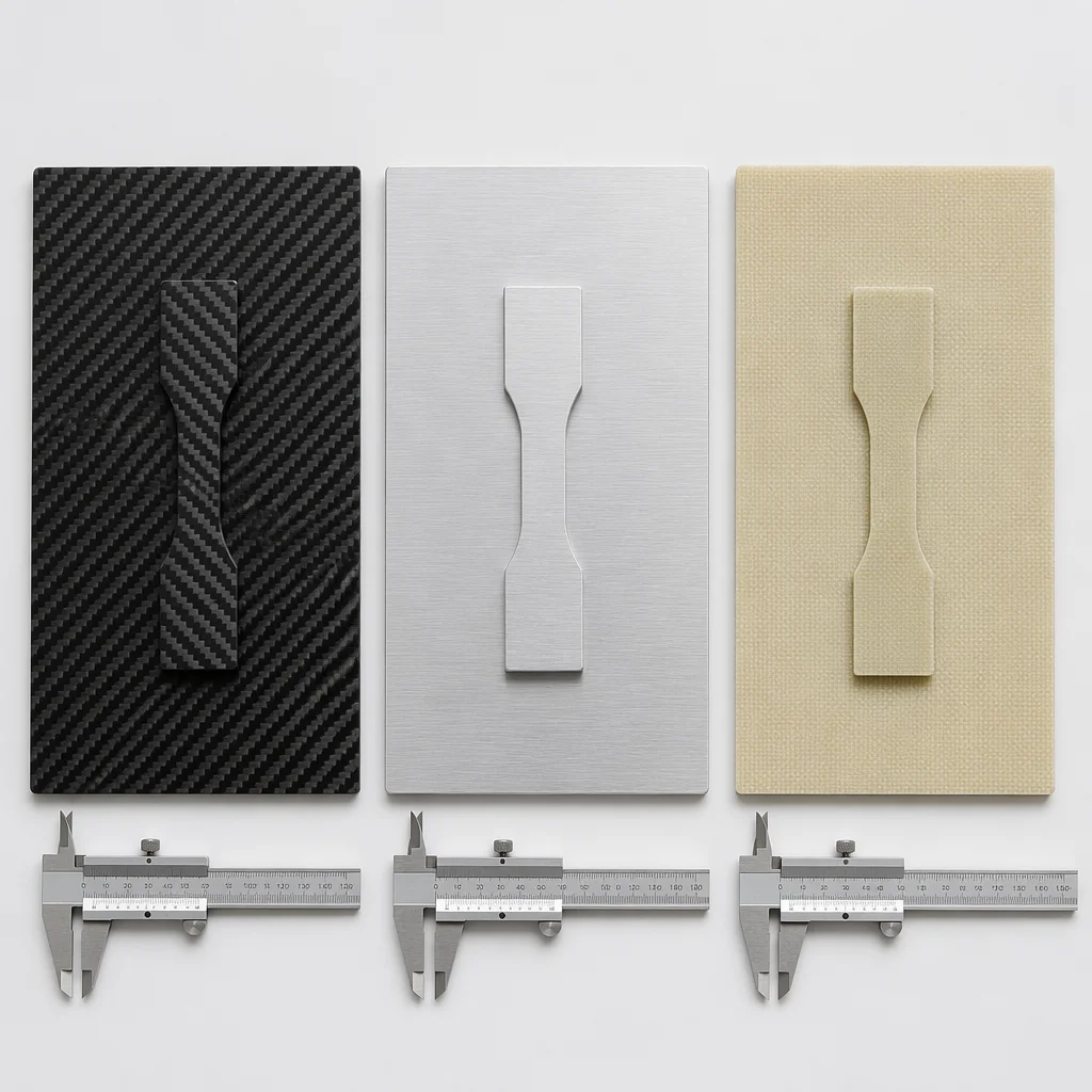
There is no universal "best" airframe material — only the material that best matches the constraints you are operating under. The decision tree is straightforward once the priorities are ranked:
- Weight budget is primary — choose carbon fiber. Accept the higher cost and plan for brittle failure modes in your structural margins and spare parts strategy.
- Impact toughness matters most — choose aluminum. The weight penalty buys you plastic deformation and field-repairable bent parts that keep aircraft flying between depot cycles.
- RF transparency is non-negotiable — choose G10/FR4. Carbon fiber near antennas or compasses creates problems that are hard to diagnose and harder to fix without a frame redesign.
- Cost sensitivity drives decisions — G10 or aluminum, depending on the mechanical loads. Aluminum where threads and toughness matter, G10 where RF and electrical isolation matter.
- Production volume is scaling — consider CNC-routed aluminum or waterjet G10 panels. Both scale more predictably than hand-laid carbon, though molded carbon tooling becomes competitive at higher quantities.
Many production UAVs use hybrid approaches: carbon fiber arms and booms for stiffness and weight, aluminum motor mounts and landing gear for toughness and threadability, and G10 plates wherever antennas or GPS modules need an RF-transparent window. A hybrid frame is not a compromise — it is deliberate material allocation to the loads each structural zone actually sees.
Education, not a specification
This article provides an industry overview of airframe material trade-offs. It is not a certified design guide, an engineering specification or a substitute for structural analysis against your specific loads, safety factors and regulatory requirements. Material properties cited are typical values from manufacturer data sheets; your supplier's batch certificates should govern procurement decisions.